ENGINE FUEL SYSTEM
FUEL DISTRIBUTION
The fuel distribution system supplies fuel from tanks to the engines. The
fuel is metered, filtered and supplied at the pressure and flow rate
necessary to enable stable engine operations during all the phases. The
metered Fuel Flow (FF) is sent to the fuel nozzles for combustion, and
pressurized fuel is supplied to the fuel-operated actuators of the engine
(e.g. Air valves). The fuel is also heated to prevent ice formation and
used to cool engine oil and Integrated Drive Generator (IDG) oil.
The distribution system consists of:
- The Integrated Fuel Pump and Control (IFPC),
- A fuel manifold,
- Fuel/Oil Heat Exchangers (FOHEs),
- A fuel filter,
- Flow Divider Valve (FDV),
- Fuel nozzles,
- Ecology collector tank,
- Return-To-Tank (RTT) valve.

FUEL FEED FROM AIRCRAFT
When the ENGine MASTER Lever is selected ON, the Low Pressure
Shut-Off Valve (LPSOV) opens and fuel from the aircraft tanks flows
through the main fuel supply line to the inlet port of the boost pump in
the IFPC.

FUEL FEED FROM AIRCRAFT
HEAT EXCHANGERS AND FUEL RETURN TO TANK
The boost pump sends LP fuel from the engine fuel supply line to the
IDG FOHE. Fuel flow is used to cool down the IDG oil through the IDG
FOHE and the engine oil through the engine FOHE. In turn, fuel is heated
and de-iced.
Fuel from the engine FOHE is then sent to the fuel filter.
The Fuel Return-To-Tank (FRTT) module contains the Fuel Return Valve
(FRV) and the FRTT Temperature sensor.
The FRV controls fuel to flow back to the aircraft tanks from downstream
of the IDG FOHE and before it enters the engine FOHE as part of the
fuel heat management system. The FRV is controlled by the Electronic
Engine Control (EEC) depending on the fuel temperature.
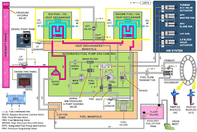

HEAT EXCHANGERS AND FUEL RETURN TO TANK
INTEGRATED FUEL PUMP AND CONTROL
The IFPC is an electronically controlled unit which integrates the fuel
metering components and the fuel pumps in a single unit to limit the
space and the number of external tubes required for the system. The IFPC
uses dual coil torque motors and solenoids to control hydro-mechanical
valves in relation to the fuel flow. The Main Gearbox (MGB) turns the
IFPC input shaft which drives the fuel pump boost-stage, the main fuel
pump and servo pump.
FUEL FILTER AND MAIN PUMP
The heated fuel from the engine FOHE is directed through the fuel
filter. The filter element is a disposable filter located in a housing
attached on the fuel manifold. The filter is monitored by a differential
pressure transmitter. The filter housing is fitted with a bypass valve
in case of filter element clogging. The filter element is a disposable
25 micron filter.
The fuel exits the fuel filter and flows to the inlet port of the main
fuel pump. The main fuel pump is a single-stage gear pump, which
increases the fuel pressure and sends the pressurized fuel to the Fuel
Metering Valve (FMV).

INTEGRATED FUEL PUMP AND CONTROL - FUEL FILTER AND MAIN PUMP
INTEGRATED FUEL PUMP AND CONTROL (continued)
FUEL METERING VALVE AND HIGH PRESSURE
SHUT-OFF VALVE
The EEC controls a dual Torque Motor (TM) which positions the
FMV in the desired position. The close loop monitoring is ensured
by the EEC using the valve LVDT feedback signals.
The fuel from the FMV is directed to the High Pressure Shut-Off
Valve (HPSOV). The fuel pressure at the back side of the HPSOV is
controlled by the Thrust Control Malfunction (TCM)/Overspeed TM
and allows the valve to open or close.

INTEGRATED FUEL PUMP AND CONTROL - FUEL METERING VALVE AND HIGH PRESSURE SHUT-OFF VALVE
INTEGRATED FUEL PUMP AND CONTROL (continued)
PRESSURE REGULATING VALVE AND BYPASS
DIRECTIONAL CONTROL VALVE
Inside the IFPC, the fuel from the main pump is directed to the FMV
and to the Pressure Regulating Valve (PRV). The purpose of the PRV
is to maintain a constant fuel pressure drop across the FMV to ensure
the correct fuel flow and acceleration for the engine.
The TCM/Overspeed TM controls the fuel pressure to the back side
of the PRV to modulate fuel flow between the FMV and the Bypass
Directional Control Valve (BDCV).
Pressurized fuel that passes through the PRV is directed to the BDCV.
The BDCV directs fuel by-passed by the PRV to the engine FOHE
at low engine power or when the fuel temperature is low to help in
maintaining the engine oil and fuel within operating limits.
At high power, the BDCV returns the recirculation flow downstream
of the FOHE.
INTEGRATED FUEL PUMP AND CONTROL (continued)
EEC CONTROL
The EEC controls the dual TCM/Overspeed TM for HPSOV
positioning.
It monitors the valve fully closed position with the two proximity
switches.
The EEC also controls the FMV position via a dual channel Torque
Motor (TM).
A dual channel Linear Variable Differential Transducer (LVDT)
provides the FMV position to the EEC.
For the air system, the EEC controls the fuel-operated actuators with
dual channel TMs and it monitors their position thanks to LVDT
position feedbacks.
FUEL FLOW TRANSMITTER, FLOW DIVIDER VALVE
AND FUEL NOZZLES
The metered fuel from the FMV crosses the HPSOV and flows to the
fuel flow transmitter.
The fuel flow transmitter sends the fuel flow rate to the EEC channel A
and directs fuel to the Flow Divider Valve (FDV).
The EEC commands the FDV opening during starting to improve fuel
atomization.
During engine start, the FDV sends most of fuel to the primary manifold.
Above idle, the FDV evenly divides metered fuel flow between the
primary and secondary fuel manifolds.
At shutdown, the FDV is spring loaded closed to allow primary and
secondary manifold drainage.
The FDV is fitted with a metal screen strainer that can be bypassed in
case of blockage.
There are 18 fuel nozzles mounted to the outer diffuser case. All the
nozzles atomize fuel inside the combustor.
Twelve of them are duplex nozzles featuring both a primary and a
secondary fuel flow paths while six others are simplex nozzles providing
only a secondary fuel flow path

SERVO FUEL AND SERVO MINIMUM PRESSURE AND
PUMP SHARING VALVE
The servo pump housed in the IFPC is a gear-stage pump which sends
pressurized fuel to a wash filter. Fine filtered, pressurized fuel from the
wash filter is supplied to the engine air system actuators where it is used
as servo and muscle pressure to position the actuator pistons.
These actuators are:
- the Low Pressure Compressor (LPC) Stator Vane Actuator (SVA),
- the LPC (2.5) Bleed Valve Actuator (BVA),
- the turbine Active Case Cooling (ACC) valve,
- and the High-Pressure Compressor (HPC) SVAs (primary and
secondary).
The fuel from the actuators is filtered again before it returns back to main
pump and servo pump inlet.
The Servo Minimum Pressure and Pump Sharing Valve is a spring loaded
valve that provides the five air system actuators with main pump fuel
pressure when servo pump fuel pressure is not enough during start

ECOLOGY SYSTEM
At engine shutdown, residual fuel in the manifolds downstream of the
FDV is drained back through the FDV to an ecology collector tank.
The collected fuel remains in the ecology collector tank until the next
engine start when the fuel is drawn back into the fuel system.
During shutdown, the fuel pressure from the IFPC is reduced and the
FDV closes to prevent fuel from entering the combustor and to drain any
fuel remaining in both the primary and secondary fuel lines to the ecology
collector tank.
The ecology collector tank has enough space to receive fuel from a single
engine shutdown. The tank has an inlet float valve which closes when
the tank has reached its maximum capacity. This prevents the tank from
overfilling and spilling fuel out following an aborted start.
At next engine start up, the ejector pump draws the fuel from the ecology
collector tank back to the IFPC boost pump. The tank has an outlet float
valve which closes when the tank has reached its minimum capacity and
a check valve to avoid fuel transfer from the suction line.

STARTING
INITIATION
During starting, the servo pump fuel pressure is not enough to control
the air system actuators and to close the Servo Minimum Pressure
and Pump Sharing Valve. In this position, the Servo Minimum
Pressure and Pump Sharing Valve directs a portion of pressurized fuel
from the main pump to the five actuators. The other portion of fuel
from the main pump is sent to the PRV and to the FMV. The PRV
opens partly and directs the excess of fuel flow to the BDCV which
is spring loaded to send it to the engine FOHE.
The EEC opens the FMV and let the fuel to flow to the HPSOV which
also opens and sends fuel to the fuel flow transmitter.
The pressurized fuel opens the FDV. The FDV partly opens and sends
most of fuel to the primary fuel nozzles.

STARTING (continued)
ACCELERATION
As the pumps rotation speed increases with the engine acceleration,
the fuel pressure also increases. The FMV opens more and as a
consequence the fuel pressure pushes the BDCV out of its rest position
to direct the excess fuel flow to the fuel filter.
The FDV also opens more and evenly divides metered fuel flow
between the primary and secondary fuel nozzles.
In parallel, the fuel pressure from the servo pump increases and pushes
the Servo Minimum Pressure and Pump Sharing Valve, segregating
the burn flow from the servo fuel.
SHUTDOWN
NORMAL SHUTDOWN
During a normal engine shutdown, the Master Lever controls the
LPSOV to close and sends a shutdown signal to the EEC.
As a consequence, the EEC controls the TCM/overspeed TM that
directs fuel pressure to the back side of the HPSOV to close it and
stop the fuel flow to the engine. In the same time, the PRV is
controlled fully open to bypass the main pump fuel flow away from
the FMV to the FOHE.
In turn when the related fuel pressure drops, the FDV closes to let the
remaining fuel in the nozzle manifolds to drain in the ecology drain
tank, and the Servo Minimum Pressure and Pump Sharing Valve
reopens.
After the HPSOV is confirmed closed by the proximity switches, the
EEC tests the FMV via its TM then closes it.

SHUTDOWN (continued)
ABNORMAL SHUTDOWN
The abnormal shutdown is initiated in case of an overspeed (N1 or
N2), shaft shear (fan, LP or HP) or Thrust Control Malfunction (TCM)
event detected on ground.
In such case, the TCM/overspeed TM directs fuel pressure to the back
side of the HPSOV and of the PRV. This causes the PRV to open and
stop fuel flow to the FMV, allowing rapid closure of the HPSOV and
rapid engine shutdown.
Fuel flow through the PRV is directed to the BDCV and then to the
engine FOHE.
This shutoff method is independent from the FMV control.

FUEL INDICATING
The engine fuel indicating monitors the system condition and provides
the system status to the cockpit displays.
The fuel flow transmitter sends signals to the EEC which enables the
calculation of the fuel flow to the combustor.
The fuel flow is a primary engine parameter and is displayed on the EWD
permanently. The EEC also sends this data for the fuel used computation
and display on the System Display (SD).
The Fuel Filter Differential Pressure (FFDP) sensor measures the
differential pressure across the fuel filter.
This helps to detect if the filter is partially or totally clogged.
According to the received value, the EEC will generate various warnings
on the EWD: ENG X FUEL FILTER DEGRAD or ENG X FUEL
FILTER CLOG or ENG X FUEL SENSOR FAULT and on the SD:
CLOG.
The IDG Fuel-Oil Heat Exchanger (FOHE) differential pressure sensor
is used to sense the differential pressure on the fuel side of the FOHE
and send a signal to the EEC in case of clogging detection. According to
the status, the EEC will generate various warnings on the EWD: ENG X
HEAT EXCHANGR CLOG or ENG X FUEL SENSOR FAULT.
For monitoring and Thermal Management System control by the EEC,
the fuel temperature is sensed by two dual channel temperature sensors.
The fuel temperature sensor is used for the control of the heat exchangers
(Fuel/Oil Heat Exchanger Bypass Valve (FOHEBV)) and BDCV.
The Fuel Return To Tank (FRTT) temperature sensor is used for the
RTTV control.
The engine fuel temperature is not directly displayed in the cockpit but,
according to the status, the EEC will generate various warnings on the
EWD: ENG X HOT FUEL or ENG X FUEL HEAT SYS or ENG X
HEAT SYS DEGRADED or ENG X HEAT SYS FAULT
FUEL INDICATING


0 Comments